How to Make a 433MHz RF Remote Quad-Channel Relay Switch
[ad_1]
Today we will build a 433MHz-based RF remote control switch with a four-channel relay to switch on or off up to four connected AC devices, such as a light, fan, electronic door, etc., wirelessly. The receiver module can be installed in any traditional or standard switchboard for controlling the devices.
Why Build an RF Remote Relay Switch?
Nowadays, you can purchase or build a DIY smart Wi-Fi switch and use them to control your AC devices over Wi-Fi. However, it’s not always possible to get a Wi-Fi signal in every corner of your premises. Moreover, they won’t work if the internet is down. In such cases, a 433MHz-based RF switch can be really helpful. The one we are going to build offers a decent range of 50-100 meters and works reliably well.
You can install and use this RF switch to toggle or control any light or AC load where wiring isn’t possible. By installing an RF switch, you can avoid any electrical work that might otherwise be required. For instance, we use it to open the garage door when we reach home, or the main electronic door using the transmitter module wirelessly when someone is at the door. You can build multiple transmitters to control the same receiver module when in range. We have one in our car and another at home.
Things You’ll Need
To build an RF switch, you will need the following:
- A 433.92 MHz ASK transmitter and receiver modules
- HT12E encoder and HT12D decoder ICs
- A single-, dual- or quad-channel SPDT 5V relay module (based on the number of devices you want to control)
- Push-button switch
- General PCB board
- Soldering iron and solder
- 9V battery for the transmitter and 5V supply for the receiver module
- 3D printed enclosure (optional) or any box
Solder All Parts on a General PCB
Refer to the following circuit diagrams to assemble and solder all the components for the transmitter and receiver modules. If you have never soldered before, here’s a guide to learning how to solder.
RF Transmitter Circuit
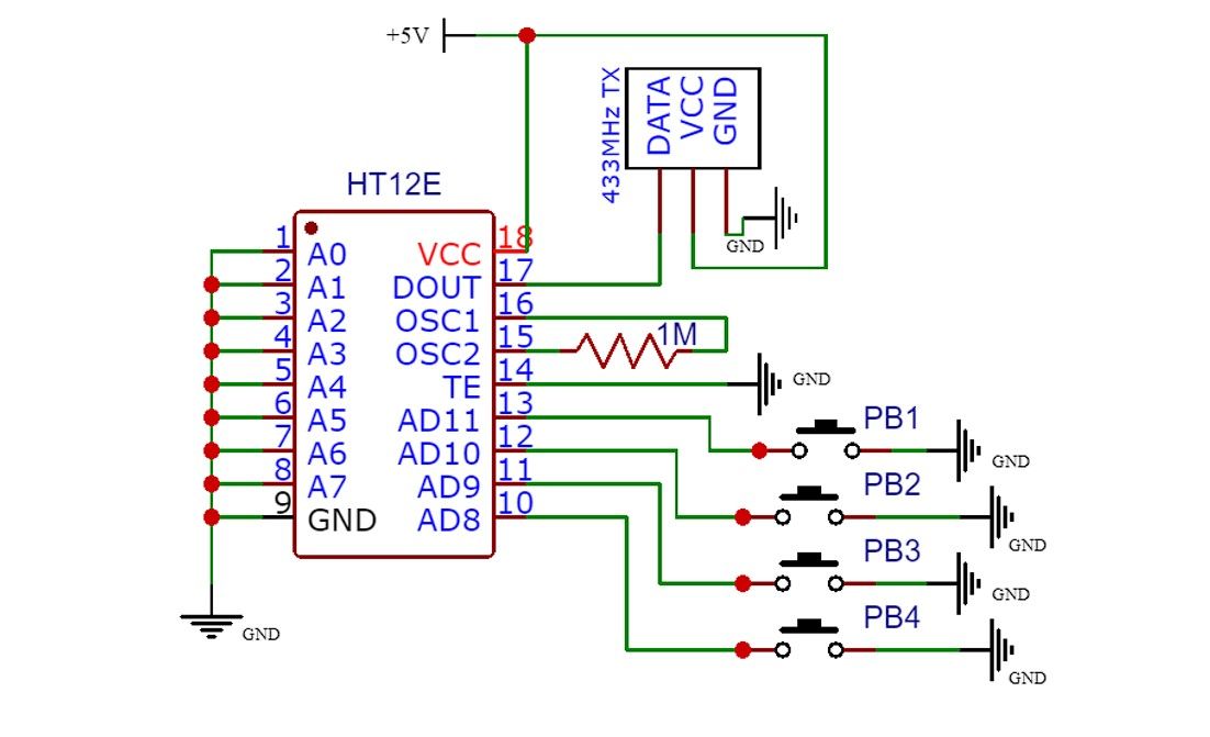
The transmitter circuit does not require many components. All you need is an HT12E encoder IC, a 433MHz RF transmitter module, a 1M resistor, and four push buttons.
RF Receiver Circuit
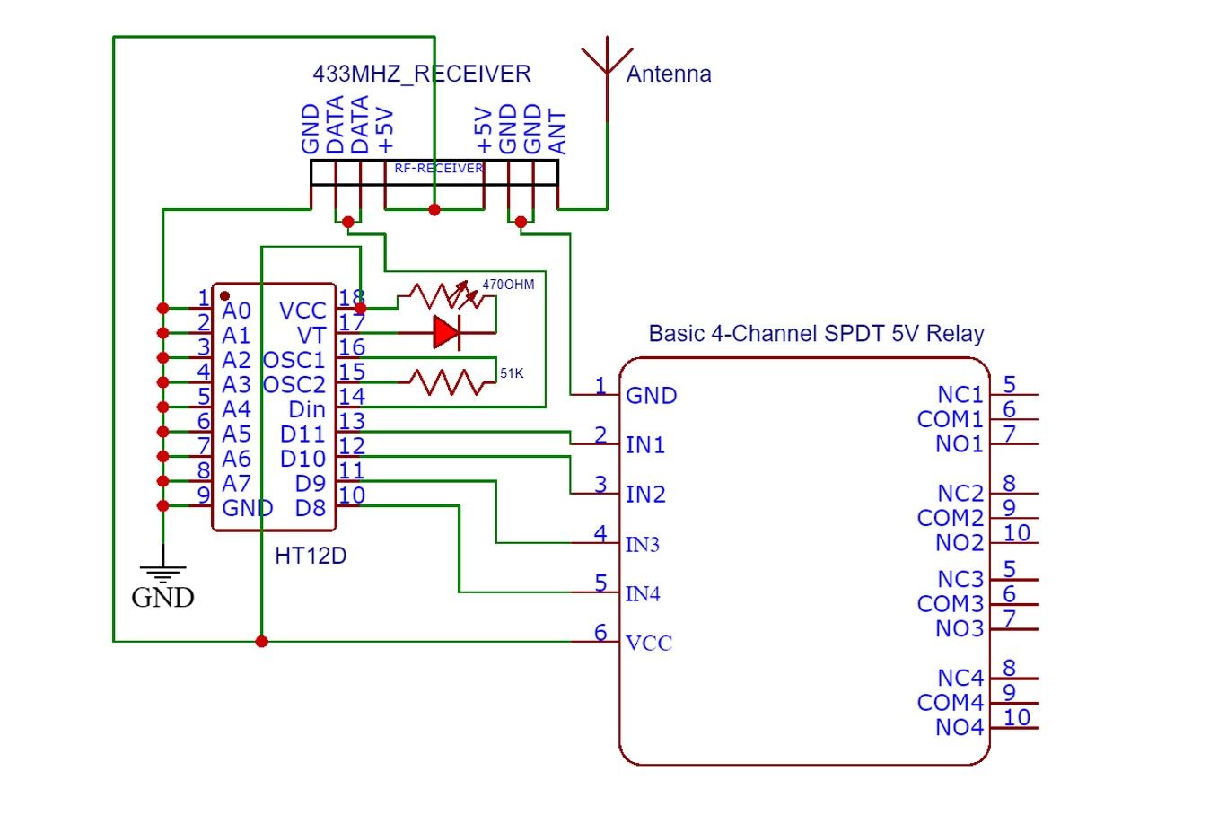
For the receiver circuit, you need an HT12D decoder IC, two resistors, an RF receiver module, an LED, and the four-channel SPDT 5V relay module.
Circuit Explanation
We are using the HT12E encoder IC on the transmitter circuit (Tx) and the HT12D for the receiver (Rx) circuit. Both are capable of encoding and decoding 12 bits of information that can consist of up to eight address bits and four data bits:
- The HT12E and HT12D have 18 pins.
- Pins 1, 2, 3, 4, 5, 6, 7, and 8 on the HT12E and HT12D are the eight address bit pins, while pins 10, 11, 12, and 13 are the four data bit pins. On Tx, the four data bit pins are used to send data; on the Rx circuit, these pins go high or low based on the signal received from the Tx.
- The eight address bit pins are connected to ground while the four data bit pins of the HT12E are connected to one of the terminals of the push buttons and the other terminal is connected to ground.
- Pins 9 and 18 on the HT12E and HT12D are the ground (-5V) and VCC (+5V) pins respectively.
- Pin 14 on the Tx circuit is Transmission Enable (TE) pin which is connected to the ground to enable data transmission.
- Pin 14 on the Rx circuit is the Data Input (DI) pin that receives the serial data from the RF receiver module, which is then decoded by the HT12D IC.
- Pins 15 and 16 on both ICs are the oscillator pins. Connecting them with a 1MΩ resistor on Tx and 51Ω on the Rx circuit enables the internal oscillator.
- Pin 17 is the Data Output (DO) pin connected to the RF transmitter module.
- Pin 17 on the receiver module is the Verify Transmission (VT) pin connected to the LED (which turns on when Rx and Tx are in range and on the same address).
When a button is pressed on the Tx circuit, a low signal is applied to the transmitter. Based on the eight address bit pin connections with ground, HT12E encodes the data into a serial form, which is modulated and sent into the environment via the RF transmitter module.
When the data is received on the Rx circuit, it is sent to the Data Input pin (14). The information is then decoded, and a high signal is sent to one of the four data bit pins on the Rx circuit.
The data pin on the Rx circuit is connected to the relay module, which triggers when a high signal is received and turns on the connected AC load.
Other Applications of RF Tx and Rx Circuits
Besides switching a connected AC load on/off, you can also use this circuit to build many other projects. You can also pair this circuit with a NodeMCU or D1 Mini for long-range wireless data transmission and integrate it with a Home Assistant server for automation.
Below are a few examples where you can use this RF Tx and Rx circuit.
- Access control systems
- Wireless home security systems
- Wireless doorbell
- Robot or toy car remote control
- Basic home automation, such as a remote light or switch
- Wireless alarm systems
- Wireless control for various types of home appliances and other electronics projects
Alternative to Wi-Fi Smart Switches
With an RF wireless transmitter and receiver switch, you can overcome the challenges and limitations of smart switches that require a Wi-Fi network to work. You can create multiple Rx circuits and control them with one Tx.
You may also change the address pin connection in Rx and Tx to use the different transmitters for different AC switches. Just make sure that the RF Tx and Rx circuits’ eight address bit pins are connected in the same order in both Rx and Tx to work. Changing the address pin connection on Tx will require changing the address pin connection on the Rx circuit. Otherwise, they won’t pair or work.
[ad_2]
Source link


